Technical Section
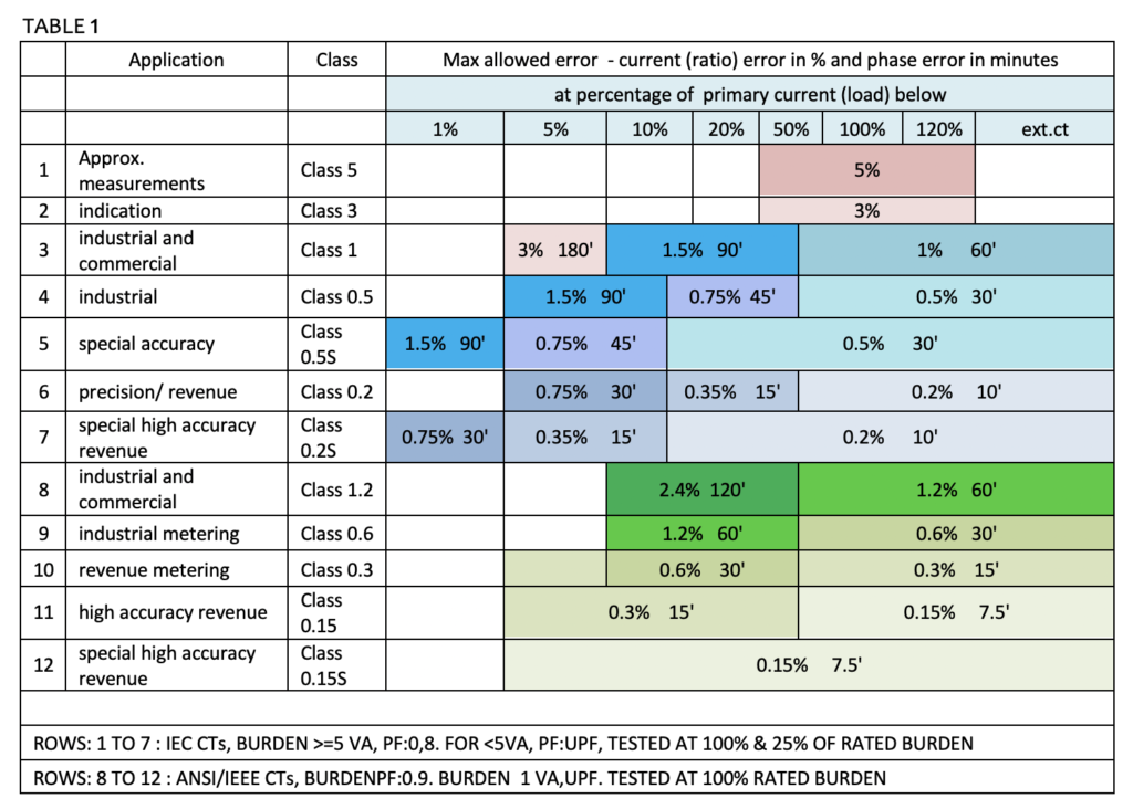
Accuracy classes for measuring CT s: The accuracy that the CT has to maintain over a specified range of primary current and secondary burden. Special high accuracy metering classes need to be accurate over a larger range of currents. These are used for high accuracy revenue metering when used with meters with wide dynamic range. Table 1 specifies the accuracy requirements and applications of various classes of CT s, according to IEC 60044, 61869 and ANSI C57.13 series.
Instrument security factor (factor of security): This typically takes a value of less than 5 or less than 10 though it could be much higher if the ratio is very low. If the factor of security of the CT is 5, it means that the composite error of the metering CT at 5 times the rated primary current is equal to or greater than 10%. This means that heavy currents on the primary are not passed on to the secondary circuit and meters are therefore protected.
Class P CT s are specified by their saturation behaviour under symmetrical short circuit current conditions The composite error is limited to 5% and 10% for accuracy class 5P and 10P at ALF times the rated primary current.
Composite error: The RMS value of the difference between the instantaneous primary current and the instantaneous secondary current multiplied by the turns ratio, under steady state conditions.
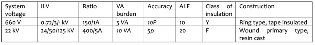
Accuracy limit factor (ALF): The value of primary current upto which the CT complies with composite error requirements. This is typically 10, 15 or 20, which means that the composite error of the CT has to be within specified limits at 10, 15 or 20 times the rated primary current.
Secondary limiting emf: ALF * rated sec current * vector sum of rated burden and impedance of sec winding.
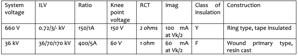
Class PS/ PX/ X CT: In balance systems of protection, CT s with a high degree of similarity in their characteristics are required. These requirements are met by Class PX (PS or X) CT s. Their performance is defined in terms of a knee-point voltage (KPV), the magnetizing current (Imag) at the knee point voltage or ½ or ¼ the knee-point voltage, and the resistance of the CT secondary winding corrected to 75 C. Accuracy is defined in terms of the turns ratio.
Knee point voltage: That point on the magnetizing curve where an increase of 10% in the flux density (voltage) causes an increase of 50 % in the magnetizing force (current).
Dimensioning factor Kx : Secondary current upto which the CT is required to maintain performance/ rated secondary current Knee point Voltages (KPV or Vk) are calculated based on the system parameters, short circuit level referred to the CT secondary, CT resistance (RCT), relay burden, lead burden to and from the relay. Economical and compact CT design can be achieved by sharing the Vk formula rather than the Vk voltage value, due to the tendency to over- or under-estimate the CT winding resistance (RCT)
Saturation flux is the max value of secondary linked flux which corresponds to magnetic saturation of the core. Remanent flux is that which remains in the core three minutes after interruption of saturation, and remanent factor is the ratio of the two.
Rated symmetrical short-circuit current factor Kssc: Ratio of the rated primary short circuit current to the rated primary current.
Class PR CT s are the same as Class P CTs, except that the remanence factor is limited to 10%
Class PXR CT s are specified as IN Class PX CT s, except that the remanence factor is limited to 10%. These CT s are able to handle a continuous low DC component during faults. CT s are air-gapped.
Class TPX, TPY and TPZ CT s are specified by their saturation behaviour under transient short circuit current conditions. The peak instantaneous error is limited for TPX and TPY CT s and the peak alternating error is limited for Class TPZ CT s. Remanence factor is limited to 10% for TPY CT s. Secondary loop time constant is limited for Class TPZ CT s. These CT s can be specified in the terms of Kssc and secondary resistive burden.
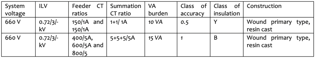
When the currents in a number of feeders need not be individually metered but summated to a single meter or instrument, a summation current transformer can be used. The summation CT consists of two or more primary windings which are connected to the feeders to be summated, and a single secondary winding, which feeds a current proportional to the summated primary current. A typical ratio would be 5 + 5 + 5/ 5A, which means that three primary feeders of 5 A are to be summated to a single 5A meter. The summated windings should be of the same phase. The feeder CT ratios need to be specified to design the summation CT correctly.
Summation CT s are always wound primary type, and are always low voltage.
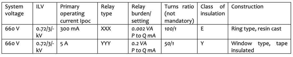
The CBCT, also known as a zero sequence CT, is used for earth leakage and earth fault protection. In the CBCT, the three core cable or three single cores of a three phase system pass through the inner diameter of the CT. When the system is fault free, no current flows in the secondary of the CBCT. When there is an earth fault, the residual current (zero phase sequence current) of the system flows through the secondary of the CBCT and this operates the relay. In order to design the CBCT, the inner diameter of the CT, the relay type, the relay setting and the primary operating current need to be furnished.
CBCT s should not be specified as metering or protection CT s . CBCT s are always low voltage and are always slot type. There is no current ratio associated with the CBCT since it does not give an output during healthy condition of system. Any ratio mentioned is the turns ratio and not the current ratio. The turns ratio is best left to the manufacturer to decide, for optimum design. The KPV of the CBCT can also be specified.