Technical Section
Instrument transformers, as the name suggests, are used with measurement and protection instruments in order to measure electrical parameters such as current and voltage or to use these parameters to activate protection schemes. The secondary side of the instrument transformer is connected to meters for measurement of current and voltage, and to protective relays for tripping circuit breakers in the event of faults.
Their role in electrical systems is of primary importance as they are a means of stepping down, accurately, the higher system current and voltage values to a measurable and standardized value of current and voltage that can be used to operate instruments. Extremely important, too, is the isolating functionof the instrument transformer.No matter how high the system voltage, the secondary circuit need be insulated only for a low voltage, thus offering ease of operation and safety to personnel.
An ideal instrument transformer would produce, in the secondary winding, a current (CT) or voltage (VT) value that is exactly proportionate and in precise phase opposition to the value in the primary winding.
However, practically, the primary and secondary ampere- turns are not equal. Some of the primary ampere-turns is drawn to magnetize the core and to supply its losses, so the transformation ampere-turns are lower than the primary ampere-turns, and this is what gets converted into secondary ampere-turns in precise phase opposition. So, both a ratio error and a phase error get introduced in the operation of an instrument transformer.
In the case of a voltage transformer, in addition, resistance and leakage reactance drops in the primary and secondary windings play a significant part in determining the errors. Secondary leakage reactance affects the errors of the CT especially during overcurrent.
Kappa CT s and VT s are designed deliver the required accuracy at rated or extended burdens without compromising on the other performance requirements such as the short time rating ( for CT) or voltage factor (for VT)requirement.
Rated primary current or voltage: The value of current or voltage which is to be transformed to a lower value
Rated secondary current or voltage: The required current or voltage in the secondary circuit, on which the performance of the CT or VT is based. Typical values of secondary current are 1 A or 5A. In the case of transformer differential protection, secondary currents of 1/ 3 A and 5/ 3 A are also specified. Typical values of secondary voltage are 110 V or 100V, or 110V/rt3 or 100 V/rt3.
Rated burden: The apparent power of the secondary circuit in Volt-amperes expressed at the rated secondary current or voltage and at a specific power factor. The burden of the circuit includes the burden of the instrument and the leads to and from the instrument.
Short time rating, STR: The value of primary current (in kA) that the CT should be able to withstand both thermally and dynamically without damage to the windings, with the secondary circuit being short-circuited. The time specified is usually 1 or 3 seconds. The dynamic rating is usually 2.5 times the thermal current. The short time rating must be complied with for the protection scheme to be meaningful.
Unearthed VT s: These VT s are intended to be connected between lines and no primary side winding can be earthed in service.Examples are double pole and three phase three limb VT s.
Earthed VT s: One end of the primary winding is earthed in service in the case of single pole VT s. The primary neutral is earthed in service to extract the residual voltage of the system in the case of three phase five limb VT s.
Rated voltage factor, Fv: Multiplying factor to be applied to the rated primary voltage to determine the maximum voltage at which the VT must meet thermal and performance requirements. Typically, 1.2 cont., 1.5/ 30 sec or 1.9/ 30 sec or 1.9/ 8 hours. The voltage factor depends on the system earthing condition. 1.2 is used for connection between phases, 1.5 for solidly earthed system, 1.9/30 secs for non-effectively earthed system with automatic fault tripping, 1.9/ 8 hrs for resonant earthed without automatic fault tripping or isolated systems.
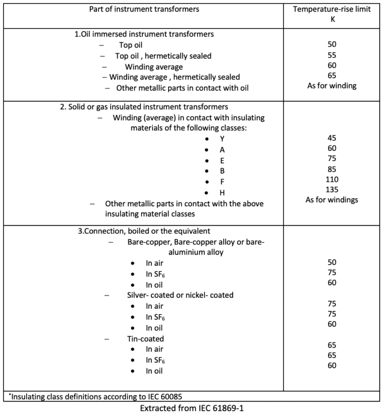
Thermal limiting output: The apparent power that the secondary can deliver at rated voltage without exceeding temperature rise limits, as given in Table-1.
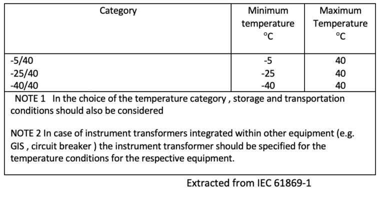
Temperature Category: The ambient operating temperature categories are defined as in Table-2
Rating factor(ANSI): A multiplying factor specified for the continuous rating of the instrument transformer upto to which it has to maintain accuracy and stay within temperature rise limits. Typical values are 1, 1.33, 1.5, 2, 3 and 4.
Extended burden for CT s: If the max burden is limited to 15VA, an extended burden with the same performance requirements can be specified down to a burden of 1 VA, with UPF over the entire range.
Extended current for measurement CT s: The CT has to maintain accuracy upto the extended current, usually 150% or 200% of the rated current. The temperature rise limits should also be maintained.
Measuring current or voltage transformer: A CT or VT that is intended to transmit an information signal to measuring instruments and meters.
Protection CT s or VT s: Those that transmit an information signal to electrical protective and control devices
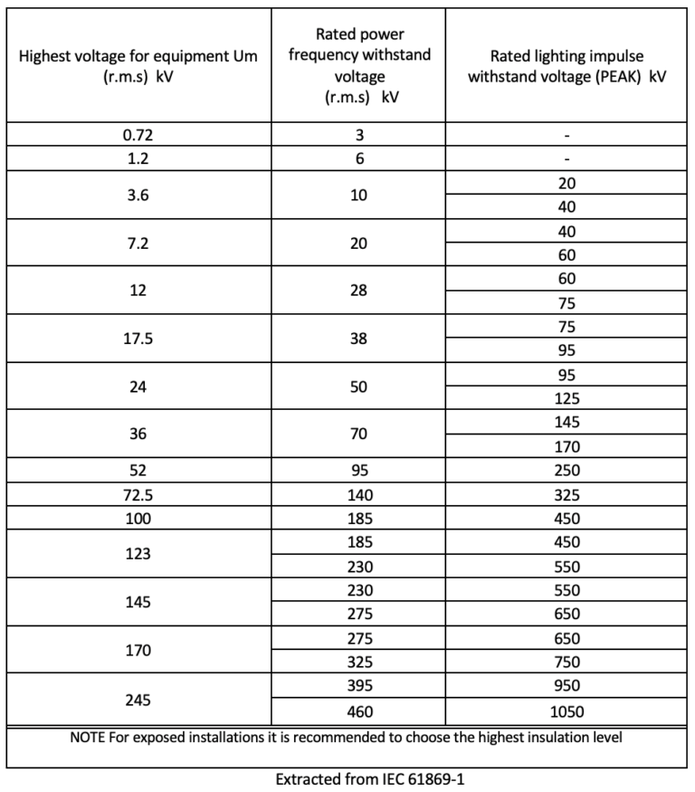
Rated insulation level: Specifies the highest continuous voltage withstand (HSV), the one-minute power frequency withstand voltage (PFW) and the lightning impulse withstand voltage (kVpeak). Table-3 below is extracted from IEC 61869-1.


Polarity is a means of designating the relative instantaneous directions of the currents/ Voltages in the primary and secondary circuits.
With reference to the diagram below, when primary current flows from P1 to P2, the secondary current will flow from S1 to S2 if the polarity markings are correct.

Winding diagram Is explained with an example
Core 1 : 600/5 A and Core 2 600-300/5A
1S1 and 1S2 relate to Core 1 – 600/5A
2S1 and 2S2 are the terminals of the 300/5A winding, Core 2
2S1 and 2S3 are the terminals of the 600/5A winding, Core 2
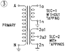
With reference to the winding diagram below, all terminals marked A or a have the same instantaneous direction, and all terminals marked N or n have the same instantaneous direction

11 kV/rt3//110V/rt3//110V/rt3 – 110V/3
A – N – 11 kV/rt3
Secondary 1 – 1a to 1n – 110V/rt3
Secondary 2 – 2a1 to 2n – 110V/rt3
Secondary 2 – 2a2 to 2n – 110V/3
A number of routine and type tests have to be conducted on IT s before they can meet the standards specified above. The tests can be classified as:
All these tests determine the healthiness of the insulation.
5.Temperature rise tests, as type test
6. Short time current tests, as type test
Kappa conducts routine tests on each and every unit produced and all designs are periodically type tested. Factory test reports are furnished for all supplies made.