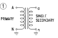
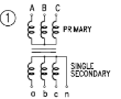
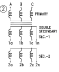
The primary of the VT is connected between line (phase) and earth.
Three such VT s can be connected in star to form a three phase bank
The primary neutral of the VT must be earthed
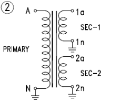
Winding diagram is as under for VT s with single secondary, double secondary, and double secondary with tappings
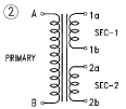
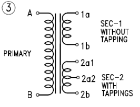
SINGLE PHASE DOUBLE POLE VT
Also called a single phase unearthed VT
The primary of the VT is connected between lines (phases)
Two such VTs can be connected in “VEE” connection to three phase bank
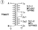
Winding diagram is as under for VT s with single secondary, double secondary, and double secondary with tappings
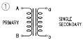
THREE PHASE THREE LIMB VT
Also called a three phase unearthed VT
The primary is connected between the three lines (phases)
The primary neutral should not be earthed
Winding diagram is as under for VT s with single secondary and double secondary VT s
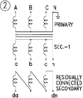
RESIDUAL VOLTAGE TRANSFORMER
Also called a three phase earthed VT
The residual voltage transformer can extract the residual voltage or the earth-fault voltage of the system, across the open delta winding.
The primary is connected between the three lines (phases)
The primary neutral must be earthed in order to detect the earth fault
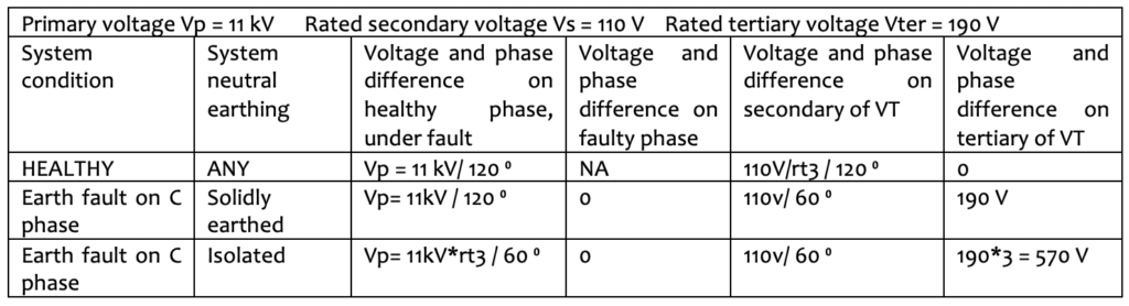
The residual voltage winding is usually rated for 110 V/3 V or 110 /rt3 V or 110 V or 190 V (Vter)
The table below shows the different possibilities of voltage across the healthy and faulty phases of the VT
Winding diagram is as under for VT s with single secondary and double secondary VT s
Multiple secondary VT s: VT s can have more than one secondary winding. However, unlike in a CT, these windings are all inter-dependent while delivering the required performance. Loading each winding will affect the errors of the other winding. The primary must be rated to deliver the most stringent class of accuracy at the sum of the burden of all the secondaries. The effect of residual voltage windings and those that will be loaded only for a short time can be ignored. Kappa offers both simultaneous and individually loaded windings depending upon the application.
VT protection: Fuse protection is typically used in the primary winding. But the MCB or fuse protection of the secondary is more important, and must be located as close to the secondary terminals as possible. The errors of the VT are measured with fuses in place, when supplied with the VT s.
MEASURING (METERING) VTs
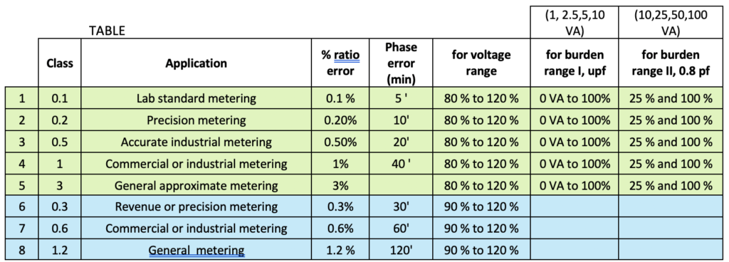
Accuracy classes for measuring VTs: The accuracy that the VT has to maintain over a specified range of primary voltages and secondary burdens, as given in the table below .
ROWS 1 TO 5 ARE IEC / IS VTs WITH PF AS SHOWN IN TABLE
ROWS 6 TO 8 ARE ANSI VTs WITH BURDENS W,X,M,YZ,ZZ WITH PF: 0.1, 0.7, 0.2, 0.85,0.85,0.85
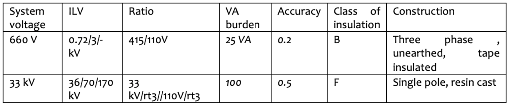
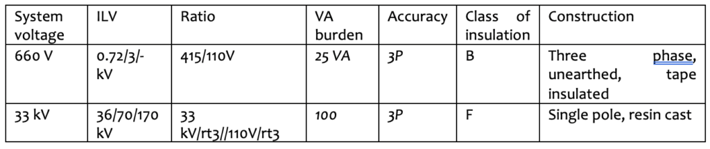
Typical specifications
PROTECTION VTs
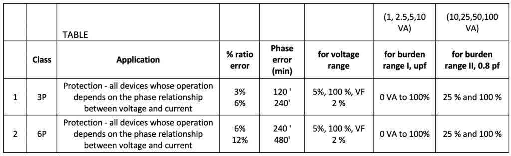
Accuracy classes : 3 P and 6 P with range of measurement is given in the table below$
Every protection VT must also be allotted a measurement class of accuracy.
Typical specifications
FERRO-RESONANCE
Ferro-resonance drives a VT from its normal steady state behaviour at power frequency to a ferro-resonant steady state characterized by high voltages and harmonics that can seriously damage the equipment. Oscillations are set up between the non-linear inductance of the saturated VT and the capacitance of the network.
An isolated neutral system, even unintentionally isolated at any point, is most favourable to ferro-resonance. The ferro-resonant stage is unpredictable and depends on a number of factors such as a lightly loaded or unloaded VT, sudden opening of a circuit breaker (VT is fed through grading capacitance of breakers), non-multipole breaking of circuit, switching operations, etc. Ferro-resonant behaviour is unpredictable, and depends also on the residual flux in the core of the VT at the time of occurrence.
The behaviour can be mitigated by choosing VT s that are designed accordingly. The susceptibility of the system must be evaluated and Kappa can offer suitable VT s.
Another alternative is the insertion of a damping resistance across the open delta to dampen the oscillations. The resistor rating has to be sufficient to dampen. Kappa VTs come with additional damping winding in high accuracy VTs.